 Germany
 Italy
Italy USA
USA South Korea
 UK
UK India
India France
 China
China Japan
Japan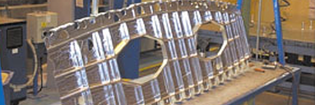
Flying High at Airbus
Airbus is selling so well that the demand to increase build rate has never been higher. BAE Systems (Filton, UK) needed a simple way to improve throughput — it found the answer in VERICUT.
Modern high-speed machine tools are equipped with digital control systems incorporating very elaborate algorithms to ensure the machine does not shake itself to pieces when contouring at feeds in excess of 20m/min. These features, more commonly known as the acceleration/ deceleration curves, work extremely well in most applications.
However, BAE Systems Filton found them to be an inhibiting factor when trying to optimize the production of key components for the wing structures of Airbus planes. It wasn’t straightforward at first; you cannot simply switch such control parameters off and hope for the best. That would have lead to some very unpredictable situations. So instead, BAE Systems set about contacting tooling and software companies for a solution. The result was a very successful project involving CGTech and Kennametal.
Both companies set about optimizing the setup on Cell F, comprised of Mori Seiki SH-50 machining centers and mainly used to cut aluminum A-Frames for the A330/340 Airbus. These come in 60 variations and are situated along the leading edge of the wings. There was no need to change the fundamental setup; material already arrived on a JIT basis pre-blocked, skimmed, and drilled ready for fixtures. So it was back to optimizing feeds and speeds. OptiPath® was used to override various control parameters, while Kennametal’s tooling allowed efficient cutting at higher feeds and speeds.
VERICUT’s OptiPath reads the NC tool path file and divides motion into a number of smaller segments. Because VERICUT mathematically subtracts the material cut away from the model, the software always knows the depth/ width/angle of cut, and the amount of material removed. Where necessary, based on the amount of material removed in each segment, OptiPath assigns the best feed rate for each cutting condition encountered. It then outputs a new tool path, identical to the original but with improved feed rates. The principle is simple – the shallower the cut, the faster the feed rate. In order to keep material cutting rather than just tearing at these accelerated feed rates, the spindle speed is ramped up accordingly. For deeper cuts the reverse is applied.
“CGTech got involved helping us to get the best out of our NC programs and changing the mind set at Filton,” said Matt Godfrey, EIT team leader. “We swapped tools for ones with longer flute lengths and took greater depths of cut – and got better finishes. We didn’t have to change the part programs whatsoever. OptiPath took care of feed rates for us – we just capped the programs at 7m/min. feed rate to stop thin cuts ramping up to 16m/min. This would have given us unacceptable surface finishes for aerospace work. The original program was set up to cut at around 1m/min. We now have improved accuracy and better tool utilization.”
Filton experimented with two optimization methods: ‘Constant Volume’ and ‘Constant Chip’ thickness. Operators found the constant volume method was more suited to the A-Frames. Using this method run time was cut by 25% and throughput was in increased by 15% – with the largest savings on roughing.
To ensure the master programs are never altered, subdirectories were set up to handle the optimized versions of each program. These are downloaded over the shop floor DNC system just as any NC program. They are standard programs – the only difference is they contain optimized feeds and speeds. An attempt to do this manually would more than likely result in hours of programming time for very little benefit.
They also use OptiPath to optimize part programs for Airbus ribs which run on Cell G, equipped with the older type Marwin Automax II machining centers. These machines do not run using normal G-code. Instead they use the direct CL output from the CAM system. The CL data is processed by the machine tool itself using tool diameter, length data measured by a tool probing system. “To get around this we had a ‘reverse post’ written,” says Godfrey. The CL file is run through Expertec software to turn it into a G-code file, then it’s optimized using OptiPath and turned back into a CL file. Godfrey is currently concentrating on roughing where the savings are the greatest. So far the results have been excellent. In fact, the roughing procedure has improved so much that the swarf removal capability of the machines had to be upgraded.
A special project team is currently being assembled to roll the benefits seen on cells F and G across all five cells at the Filton plant. One cell that will particularly benefit is Cell W, a new £8 million Forest-Line installation. Cell W is comprised of three large high-speed machining centers fed by an automatic pallet system, designed to machine 330/340 Airbus ribs. “Once the programmers for this cell have finished training on OptiPath we’ll start using it,” says Godfrey.
Another Cell destined for OptiPath is cell E – Mori Seiki machining centers exclusively used in machining titanium components.

